4. Color Palettes, Sprites, second app
This Week
Now that you can make and run a program, time to put something on screen!
4.1. Palettes
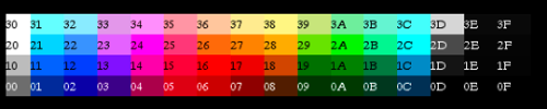
Before putting any graphics on screen, you first need to set the color palette. There are two separate palettes, each 16 bytes. One palette is used for the background, and the other for sprites. The byte in the palette corresponds to one of the 64 base colors the NES can display. $0D is a bad color and should not be used. These colors are not exact and will look different on emulators and TVs.
The palettes start at PPU address $3F00 and $3F10. To set this address, PPU address port $2006 is used. This port must be written twice, once for the high byte then for the low byte:
LDA $2002    ; read PPU status to reset the high/low latch to high
LDA #$3F
STA $2006    ; write the high byte of $3F10 address
LDA #$10
STA $2006    ; write the low byte of $3F10 address
That code tells the PPU to set its address to $3F10. Now the PPU data port at $2007 is ready to accept data. The first write will go to the address you set ($3F10), then the PPU will automatically increment the address ($3F11, $3F12, $3F13) after each read or write. You can keep writing data and it will keep incrementing. This sets the first 4 colors in the palette:
LDA #$32   ;code for light blueish
STA $2007  ;write to PPU $3F10
LDA #$14   ;code for pinkish
STA $2007  ;write to PPU $3F11
LDA #$2A   ;code for greenish
STA $2007  ;write to PPU $3F12
LDA #$16   ;code for redish
STA $2007  ;write to PPU $3F13
You would continue to do writes to fill out the rest of the palette. Fortunately there is a smaller way to write all that code. First you can use the .db directive to store data bytes:
PaletteData:
  .db $0F,$31,$32,$33,$0F,$35,$36,$37,$0F,$39,$3A,$3B,$0F,$3D,$3E,$0F  ;background palette data
  .db $0F,$1C,$15,$14,$0F,$02,$38,$3C,$0F,$1C,$15,$14,$0F,$02,$38,$3C  ;sprite palette data
Then a loop is used to copy those bytes to the palette in the PPU. The X register is used as an index into the palette, and used to count how many times the loop has repeated. You want to copy both palettes at once which is 32 bytes, so the loop starts at 0 and counts up to 32:
  LDX #$00                ; start out at 0
LoadPalettesLoop:
  LDA PaletteData, x      ; load data from address (PaletteData + the value in x)
                          ; 1st time through loop it will load PaletteData+0
                          ; 2nd time through loop it will load PaletteData+1
                          ; 3rd time through loop it will load PaletteData+2
                          ; etc
  STA $2007               ; write to PPU
  INX                     ; X = X + 1
  CPX #$20                ; Compare X to hex $20, decimal 32
  BNE LoadPalettesLoop    ; Branch to LoadPalettesLoop if compare was Not Equal to zero
                          ; if compare was equal to 32, keep going down
Once that code finishes, the full color palette is ready. One byte or the whole thing can be changed while your program is running.
4.2. Sprites
Anything that moves separately from the background will be made of sprites. A sprite is just an 8x8 pixel tile that the PPU renders anywhere on the screen. Generally objects are made from multiple sprites next to each other. Examples would be Mario and any of the enemies like Goombas and Bowser. The PPU has enough internal memory for 64 sprites. This memory is separate from all other video memory and cannot be expanded.
4.2.1. Sprite DMA
The fastest and easiest way to transfer your sprites to the sprite memory is using DMA (direct memory access). This just means a block of RAM is copied from CPU memory to the PPU sprite memory. The on board RAM space from $0200-02FF is usually used for this purpose. To start the transfer, two bytes need to be written to the PPU ports:
LDA #$00
STA $2003  ; set the low byte (00) of the RAM address
LDA #$02
STA $4014  ; set the high byte (02) of the RAM address, start the transfer
Once the second write is done the DMA transfer will start automatically. All data for the 64 sprites will be copied. Like all graphics updates, this needs to be done at the beginning of the VBlank period, so it will go in the NMI section of your code.
4.2.2. Sprite Data
Each sprite needs 4 bytes of data for its position and tile information in this order:
Y Position - vertical position of the sprite on screen. $00 is the top of the screen. Anything above $EF is off the bottom of the screen.
Tile Number - this is the tile number (0 to 256) for the graphic to be taken from a Pattern Table.
Attributes - this byte holds color and displaying information:
76543210
|||   ||
|||   ++- Color Palette of sprite.  Choose which set of 4 from the 16 colors to use
|||
||+------ Priority (0: in front of background; 1: behind background)
|+------- Flip sprite horizontally
+-------- Flip sprite vertically
X Position - horizontal position on the screen. $00 is the left side, anything above $F9 is off screen.
Those 4 bytes repeat 64 times (one set per sprite) to fill the 256 bytes of sprite memory. If you want to edit sprite 0, you change bytes $0200-0203. Sprite 1 is $0204-0207, sprite 2 is $0208-020B, etc
4.2.3. Turning NMI/Sprites On
The PPU port $2001 is used again to enable sprites. Setting bit 4 to 1 will make them appear. NMI also needs to be turned on, so the Sprite DMA will run and the sprites will be copied every frame. This is done with the PPU port $2000. The Pattern Table 0 is also selected to choose sprites from. Background will come from Pattern Table 1 when that is added later.
| PPUCTRL ($2000) | |
|---|---|
| 7 | Generate an NMI at the start of the vertical blanking interval vblank (0: off; 1: on) |
| 6 | PPU master/slave select |
| 5 | Sprite size (0: 8x8; 1: 8x16) |
| 4 | Background pattern table address (0: $0000; 1: $1000) |
| 3 | Sprite pattern table address for 8x8 sprites (0: $0000; 1: $1000) |
| 2 | VRAM address increment per CPU read/write of PPUDATA (0: increment by 1, going across; 1: increment by 32, going down) |
| 1 & 0 | Base nametable address (0 = $2000; 1 = $2400; 2 = $2800; 3 = $2C00) |
And the new code to set up the sprite data:
LDA #$80
STA $0200        ;put sprite 0 in center ($80) of screen vertically
STA $0203        ;put sprite 0 in center ($80) of screen horizontally
LDA #$00
STA $0201        ;tile number = 0
STA $0202        ;color palette = 0, no flipping

LDA #%10000000   ; enable NMI, sprites from Pattern Table 0
STA $2000

LDA #%00010000   ; no intensify (black background), enable sprites
STA $2001
4.2.4. Putting It All Together
Download and unzip the master.zip sample files. This lesson is in sprites. All the code above is in the sprites.asm file. Make sure sprites.asm, mario.chr, and sprites.bat are all in the same folder as NESASM3, then double click sprites.bat. That will run NESASM3 and should produce the sprites.nes file. Run that NES file in FCEUXD SP to see your sprite! Tile number 0 is the back of Mario’s head and hat, can you see it? Edit sprites.asm to change the sprite position (0 to 255), or to change the color palette for the sprite (0 to 3). You can choose the PPU viewer in FCEUXD SP to see both Pattern Tables, and both Palettes.